Features
Contents
1 General Information
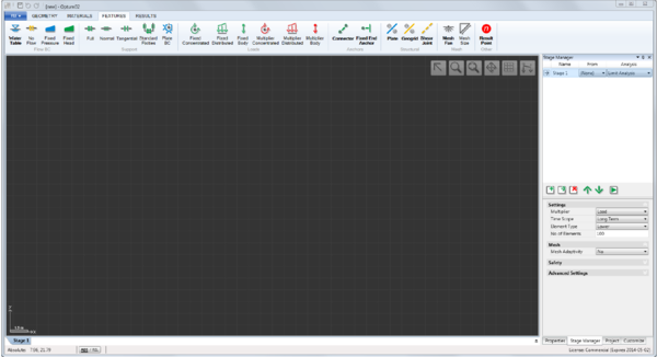
Loads, boundary conditions, structural elements, and various other features are located in the Features ribbon as shown below. All features can be applied by select-and-assign, i.e. by selecting a geometric object (e.g. a Line) and then the relevant feature in the Features ribbon. In addition, some features also work as assignment tools. For these, selecting the feature, will activate the tool, usually in the form of a cursor, and the feature can then be applied directly to the geometric object. Names of features with tool functionality, e.g. Water Table or Mesh Fan and shown in bold.
The features are organized in seven categories: Flow BC, Support, Loads, Anchors, Structural, Mesh, and Other. In the following, the features in each of these categories are documented.
2 Flow BC
The Flow BC category contains four features:
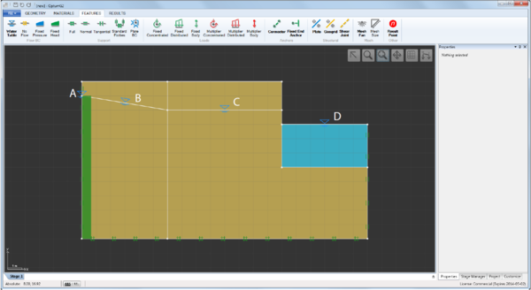
- Water Table (tool). When used as a tool, a water table is automatically assigned as indicated by the dashed blue line that appears when it is activated. When used outside solid domains, additional solids assigned the default material Water are created. When used on a vertical segment that defines an external boundary, a Fixed Head BC corresponding to a hydrostatic pressure distribution along the segment is automatically assigned. Finally, water tables may be assigned to any segment by select-and-assign (select the segment and then the Water Table feature). Some examples are shown in the figure below.
- No-Flow. This feature can be applied to Lines by means of select-and-assign. The resulting Line will act as an impermeable barrier.
- Fixed Head. This feature can be applied to Lines by means of select-and-assign. The value at the beginning and end of the segment are required as input. Also, it is necessary to select the side on which the boundary condition acts. This is important in connection with assignment to impermeable Plates and to external boundaries.
- Fixed Pressure. The pressure equivalent of Fixed Head. Note that pressures are negative in compression, i.e. below the groundwater table.
2.1 Notes
All mechanical supports (see the following section) act as no-flow boundaries.
External boundaries for which no Flow BCs have been assigned are assumed to be seepage faces, i.e. the pressure is zero while the outward flux may be non-zero (see the Theory Manual).
Flow BCs apply only with respect to the seepage pressures, ps . To also imposed conditions with respect to the excess pressures, see Section 3
3 Consolidation BC
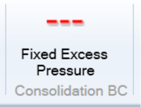
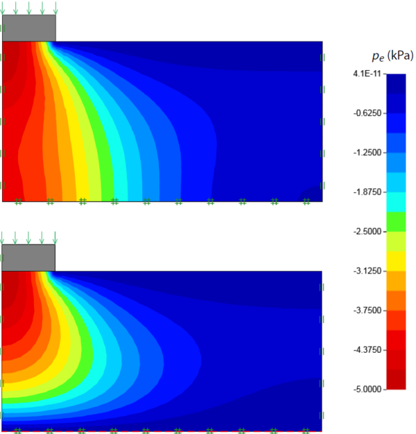
The Consolidation BC category contains a single feature: Fixed Excess Pressure which fixes the excess pore pressure to a specified value along a line. This feature is only relevant for Consolidation analysis. An example of effects of specifying a zero excess pressure (corresponding to free drainage) is shown below.
4 Support
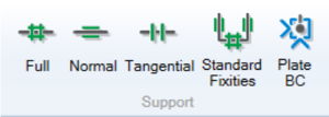
The Support category contains five features:
- Full. This feature can be applied to Lines by means of select-and-assign. The displacements in all directions along the Line are constrained.
- Normal. This feature can be applied to Lines by means of select-and-assign. The displacements in the direction normal to the Line are constrained.
- Tangential. This feature can be applied to Lines by means of select-and-assign. The displacements in the direction along the Line are constrained.
- Standard Fixities. This feature applies Normal supports to vertical Lines and Full supports to horizontal Lines that define the domain boundary.
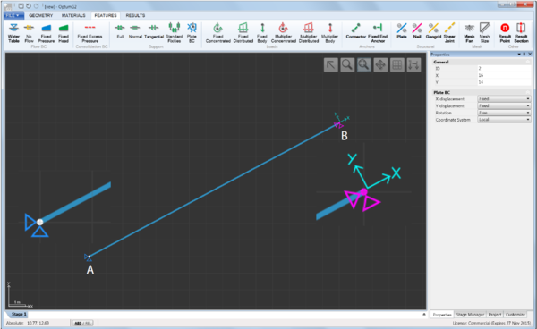
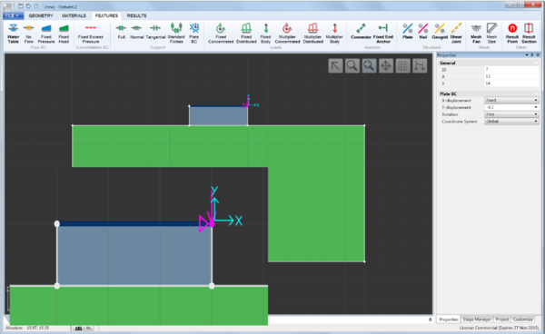
- Plate BC. This feature can be applied to Points that are part of Plates, Geogrids or Connectors by means of select-and-assign. Any or all of the three degrees of freedom (two displacements and a rotation) can be constrained and it is possible to use a local coordinate system as shown in the Figure below.
- In addition, fixed displacements can be specified (see Figure 4.2). These are relevant only for Elastic, Elastoplastic and Consolidation analysis.
4.1 Notes
Line Supports (Full, Normal, Tangential) also act as no-flow boundaries.
5 Loads
The Loads category contains a total of six different features that can be divided into two categories: Fixed loads and Multiplier loads. Fixed loads appear in green and remain at their specified value in a given stage. Multiplier loads appear in red and are, depending on the type of analysis, magnified to reach a certain value, for example the limit load in Limit Analysis. Within each category, three different types of loads are available:
- Concentrated (kN/m). These loads apply to nodes that are part of Plates or Geogrids only.
- Distributed (kN/m²). These loads apply Lines.
- Body (kN/m³ or xg). These loads apply to Solids and Plates. They may be specified either in units of force or as a fraction of the unit weight of the Solid or Plate to which they are applied.
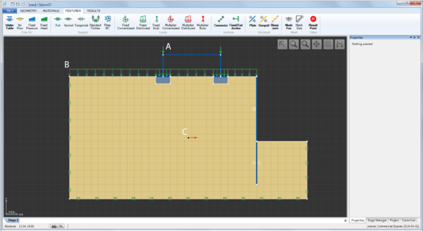
The figure below shows an example of the use of all three types of Loads: Application of Concentrated (A), Distributed (B), and Multiplier (C) loads.
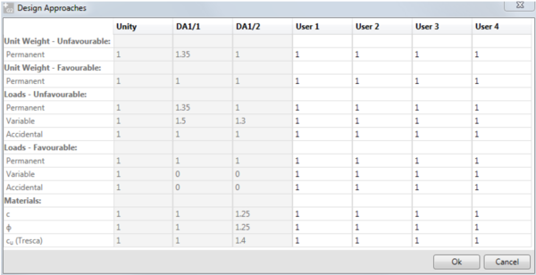
Besides their magnitude and orientation, all loads are characterized by a Load Type and a Load Category. The precise settings determine the partial factors used in the Design Approaches available for Limit Analysis and Strength Reduction (see the following figure). Load Type and Category and Design Approaches table available under Project. The set of partial factors applied, for Limit Analysis or Strength Reduction stages, depends on the Design Approach selected in these stages.
5.1 Notes
In OptumG2, unit weight (specified as part of the material properties) always acts downwards (opposite the y-axis). As such, any Body forces applied are in addition to the downwards body force due to unit weight.
6 Anchors
Anchors are one-dimensional structural elements that connect to Plates and Geogrids. There are two types of anchors, both of which work as tools:
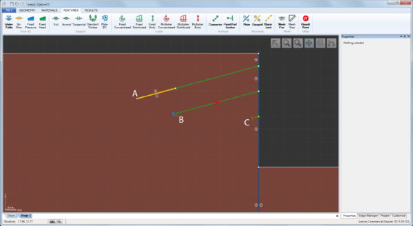
- Connectors. These are truss elements that connect to Plates and Geogrids. They do not interact with the solids, i.e. they can be thought of as existing in a layer outside the layer in which the solid domains exist. Connectors need to be assigned a material from the Connectors category. This defines the strength and stiffness of the element. In addition, it is possible to prescribe prestress to a Connector in a given stage. Prestress is indicated by the red symbol shown in the figure below.
- Fixed End Anchors. These elements can be assigned to nodes that are part of Plates or Geogrids. They are equivalent to a Connector with simple support at one end (see the figure below) and hence require specification of an equivalent length and inclination angle. Prestress can be applied in the same way as for Connectors.
Connector/Geogrid element to model a grouted anchor (A), prestressesed Connector (B), and equivalent prestressed Fixed End Anchor (C).
7 Structural
The Structural category contains three features that all work as tools:
- Plates. These are beam elements used to model walls and various other thin elements. Plates are assigned a material from the Plates category which defines its strength and stiffness properties. In addition, Plates may be either permeable or impermeable.
- Pile Rows. These are special elements that only interact partially with the soil to account approximately for what is otherwise a complex three-dimensional problem. A full description of Pile Rows is given in the Materials Manual.
- Nail Rows. This is a specialization of Pile Rows (see the Materials Manual for details).
- Geogrids. These are truss elements used to model geogrids and similar types of reinforcement. Geogrids are also commonly used to model grouted anchors (see example in the previous section and the Examples Manual). Geogrids are assigned a material from the Geogrid category which defines it strength and stiffness properties. As Plates, Geogrids may be either permeable or impermeable.
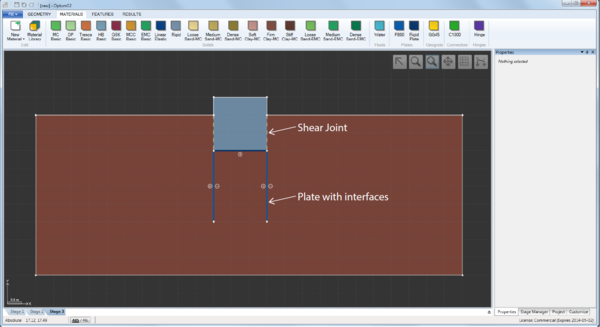
- Shear Joints. These are interface elements that may be assigned any of the materials from the Solids category. It should be noted that interfaces associated with Plates and Geogrids are an integral part of these elements and should not be defined separately. As such, Shear Joints should only be used to model internal discontinuities in solids or interfaces between solid domains. Some examples are shown below.
Plates with interfaces and Shear Joints used to model the interface between the soil and the foundation:
8 Mesh
The Mesh category contains two features:
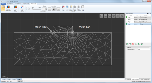
- Mesh Fan. This feature, which also works as a tool, can be applied to Points to create ‘fan’ of elements around it (see figure below). This feature is particularly useful for elements of the type Lower at points where singularities of one or another kind are present.
- Mesh Size. This features can be applied to Points, Lines and Surfaces to specify a characteristic element size. An example of application to a Point is shown below.
Specification of Mesh Size and Mesh Fan at the corners of a strip footing:
8.1 Notes
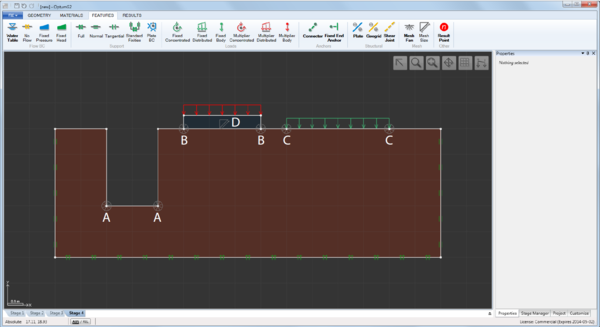
In most cases, the use of mesh adaptivity will automatically place the elements in an optimal way and there should generally be little need for manual specification of mesh sizes. However, in some cases, especially for elements of the type Lower, a manual refinement and/or specification of Mesh Fans may be useful, especially for thin solid domains or around singularities of the kind shown in the figure below.
Specification Mesh Fans at singular points (A, B, C) and Mesh Size for thin solid domain (D):
9 Other
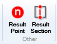
The Other category contains a single feature:
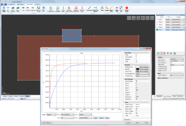
- Result Point. This features, which also works as a tool, can be applied anywhere in the domain. The results, for example of a Multiplier Elastoplastic analysis, are logged at these points and can subsequently be plotted using the XY Plots tool available under the Results ribbon.
Result Points (1 and 2) and load-displacement curves produced using XY Plots:
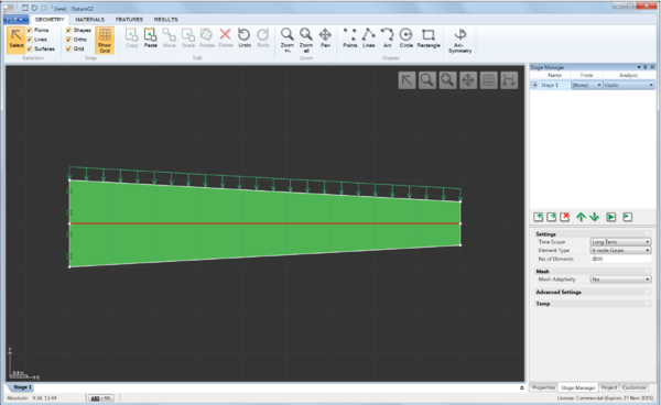
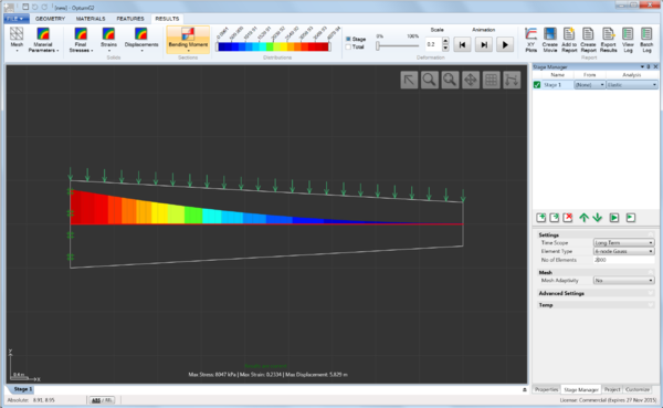
- Result Section. This features acts a “virtual plate” in the sense that Plate sectional forces (normal force, bending moment, etc) are calculated from the stresses in the surrounding elements. An example is shown below. See also the Examples manual for a full description and validation of the feature against analytical solutions.
Result Section feature applied to the center line of a tapered cantilever beam (top) and resulting bending moment distribution (bottom):
