Difference between revisions of "Features"
| Line 16: | Line 16: | ||
== Flow BC == | == Flow BC == | ||
| − | [[File:FlowBC.png| | + | [[File:FlowBC.png|200px|framelessless|center]] |
The Flow BC category contains four features: | The Flow BC category contains four features: | ||
Revision as of 09:40, 5 August 2020
Contents
1 General Information
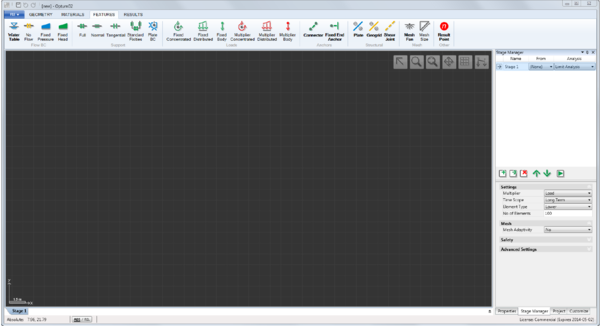
Loads, boundary conditions, structural elements, and various other features are located in the Features ribbon as shown below. All features can be applied by select-and-assign, i.e. by selecting a geometric object (e.g. a Line) and then the relevant feature in the Features ribbon. In addition, some features also work as assignment tools. For these, selecting the feature, will activate the tool, usually in the form of a cursor, and the feature can then be applied directly to the geometric object. Names of features with tool functionality, e.g. Water Table or Mesh Fan and shown in bold.
The features are organized in seven categories: Flow BC, Support, Loads, Anchors, Structural, Mesh, and Other. In the following, the features in each of these categories are documented.
2 Flow BC
The Flow BC category contains four features:
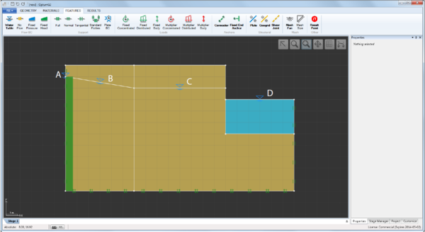
- Water Table (tool). When used as a tool, a water table is automatically assigned as indicated by the dashed blue line that appears when it is activated. When used outside solid domains, additional solids assigned the default material Water are created. When used on a vertical segment that defines an external boundary, a Fixed Head BC corresponding to a hydrostatic pressure distribution along the segment is automatically assigned. Finally, water tables may be assigned to any segment by select-and-assign (select the segment and then the Water Table feature). Some examples are shown in the figure below.
- No-Flow. This feature can be applied to Lines by means of select-and-assign. The resulting Line will act as an impermeable barrier.
- Fixed Head. This feature can be applied to Lines by means of select-and-assign. The value at the beginning and end of the segment are required as input. Also, it is necessary to select the side on which the boundary condition acts. This is important in connection with assignment to impermeable Plates and to external boundaries.
- Fixed Pressure. The pressure equivalent of Fixed Head. Note that pressures are negative in compression, i.e. below the groundwater table.
2.1 Notes
All mechanical supports (see the following section) act as no-flow boundaries.
External boundaries for which no Flow BCs have been assigned are assumed to be seepage faces, i.e. the pressure is zero while the outward flux may be non-zero (see the Theory Manual).
Flow BCs apply only with respect to the seepage pressures, ps . To also imposed conditions with respect to the excess pressures, see Section 3
3 Consolidation BC
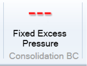
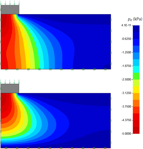
The Consolidation BC category contains a single feature: Fixed Excess Pressure which fixes the excess pore pressure to a specified value along a line. This feature is only relevant for Consolidation analysis. An example of effects of specifying a zero excess pressure (corresponding to free drainage) is shown below.
4 Support
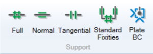
The Support category contains five features:
- Full. This feature can be applied to Lines by means of select-and-assign. The displacements in all directions along the Line are constrained.
- Normal. This feature can be applied to Lines by means of select-and-assign. The displacements in the direction normal to the Line are constrained.
- Tangential. This feature can be applied to Lines by means of select-and-assign. The displacements in the direction along the Line are constrained.
- Standard Fixities. This feature applies Normal supports to vertical Lines and Full supports to horizontal Lines that define the domain boundary.
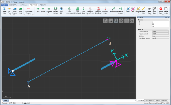
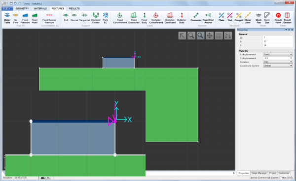
- Plate BC. This feature can be applied to Points that are part of Plates, Geogrids or Connectors by means of select-and-assign. Any or all of the three degrees of freedom (two displacements and a rotation) can be constrained and it is possible to use a local coordinate system as shown in the Figure below.
- In addition, fixed displacements can be specified (see Figure 4.2). These are relevant only for Elastic, Elastoplastic and Consolidation analysis.
4.1 Notes
Line Supports (Full, Normal, Tangential) also act as no-flow boundaries.
